In this guide, we will use Fusion 360 to convert a complex 3D model into a CAD model. Throughout this guide, you’ll learn about the various tools in Fusion 360 and the methods you need to employ to convert a model. Of course, your 3D model will differ greatly from the one used here. However, the general process and tools used in Fusion 360 will be very similar, so following this guide should give you a solid understanding of how to process a model.
And thanks to the fine folks at Autodesk for providing a free version of Fusion 360 for casual users. Some more advanced features are locked behind a paywall, but it has enough functionality to convert a 3D model into a fully functioning CAD model.
Why Make a CAD Model?
Your scan made with a Revopoint 3D scanner is an unintelligent 3D model that’s fine for things like 3D printing or importing into 3D modeling software. But when it comes to any engineering purpose like reverse engineering or rapid prototyping, the 3D model you created needs to be made smart, and this is where CAD software comes in. Once you’ve made your CAD, it’s much easier to make a model ready for manufacturing or modification.
3D Scanning
Before you can convert a 3D model to CAD, you will need to make one. And depending on the object, you need the right 3D scanner. For example, the Revopoint MINI for small things, Revopoint POP 2 for medium, and Revopoint RANGE for large objects. If you need to learn how to scan, please refer to your scanner’s user manual.
Contents
Importing and Adjusting a Model
Creating the Model’s Basic Shape
Creating Gradients
Cutting down the Model
Creating Holes
Creating Raised Lips
Creating Domes
Creating Gussets
Final Touches
_________________________________________________________________
Importing and Adjusting a Model
Before converting your 3D model into CAD, clean it up and reduce its size. Remove things like part numbers, imperfections, and casting marks, and be sure to decimate it to reduce its file size. After doing this, save your model as an OBJ or PLY file.
Open up Fusion 360 → Go to Mesh → Create → Click Insert Mesh.

It’s important at this stage to select Millimeters as the unit type for your model, or it’s likely your model will have the wrong scaling.
Click the center mesh button, and adjust your model’s orientation to a direction that works for you. Once you’ve finished adjusting it, click “Ok.”
Warning!
At the time of writing, there’s a bug in Fusion 360 that prevents you from creating a plane through 3 points if you insert your mesh. However, you can get around this by uploading the mesh, but be warned this will wreck your scaling by a factor of 10, so you’ll need to rescale your model after the upload.
Upload your model → Toggle to editable → Double click to load it into the workspace.


You may now need to adjust its position, as it’s easier to work with models when aligned to the workspace’s center.
Right-click on the model → L-click Move/Copy → Click Point to Point → Click a point on the model → Select O as a target point → Click Ok

_________________________________________________________________
Creating the Basic Shape
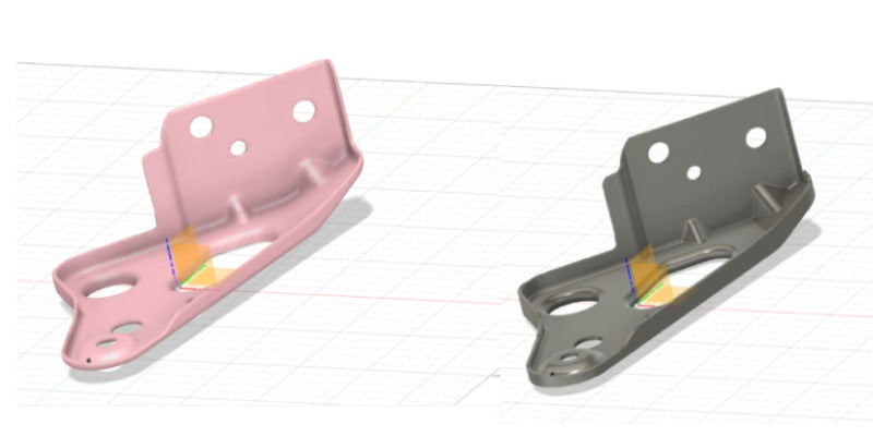
Now that the model is centered, it’s time to start converting it to a CAD model. And we’re going to start by sketching the basic shape of the bottom section.
Go to the Construct menu → Plane through 3 points → Select 3 points across your model → Ok.

Next, create a sketch: Go to the Solid Tab → Click Sketch → Select the created plain.
Now we’ll sketch around the model’s shape from a bird’s eye view. As you can see, it’s a somewhat complex shape, so we will use a few drawing tools to get an accurate sketch. But we’ll start first with the line tool.

Select the Line Tool → Draw lines along all the straight edges and ensure they intersect the line closest to them. You may have to stretch them quite a long way to do this. → Once this is done, right-click on the lines and select Fix/Unfix to keep them in place.

Don’t worry about the curves yet; we’ll get to them soon.
Select the trimming tool and cut off the excess ends of the lines so that they all end at a point.

Now it’s time to change those points into curves with the Fillet Tool. → Select the points and then drag them in to get the curved parts of the model sketched. Pay particular attention to the smaller curves that can be easy to miss.

With all the curves done, we’re ready to finish the sketch and do our first extrusion.
Go to the Solid Tab → Select Extrusion.

To get the right thickness for your model, you will need to use the measurement tool beforehand on your model. The exact settings for the extrusion depend on your object, but you can play around with them and look at your model from all angles to see which options work for you.
Creating Vertical Surfaces
Ok, you might have noticed that the part has a lot of vertical surfaces, don’t worry. We will deal with those next. So, we’re going to sketch the model we’ve just created.
Go to the Solid Tab → Select Create a Sketch → Click the New Model.
This time it’s more straightforward as all our lines and curves are much smoother. As you can see, we’ve not done any intersecting lines this time because we will use another tool to sketch the curves. So like before, draw all the straight lines first.

To deal with the curves, we’re going to use the Arc Tool.
Go to Create → Arc → Tangent/3-Point Arc

Select the line points on either side of the curve, and a line should snap around the bend. You may need to use the 3-point Arc for some of the curves to get an accurate curve.
Once you’ve finished sketching, we will need to offset this line to create the thickness of the vertical parts. So first, we measure the width and height of the highest verticle part.
Inspect → Select Measure, then zoom and carefully select the points on either side of the face you want to measure to make it as accurate as possible.

Now that we know the size, it’s time to offset. Click the Offset button → Select the sketch’s outline and enter the measurement → Click Ok, and finish the sketch.

Ok, now it’s time to extrude the model’s vertical surfaces.
Go to the Solid Tab → Select Extrude → Click on the Offset Outline → Change Operation to Join → Adjust the Size → Click Ok.

When you do this, ensure that “Join” is selected in the operation settings, as we want this to connect to the base plate to form one complete model. As you can see below, we’ve extruded to the highest point on our model because it’s easy to cut it down to the correct size later.
___________________________________________
Creating Gradient Surfaces
Right, it’s time to tackle the upwardly sloping part of the base plate because ours, at the moment, is perfectly flat.
Go to Construct → Plane through 3 points → Select 3 points across the sloping part → Click Ok.

Place 3 points on the slope so the plane follows the gradient, be warned this may take a few attempts to get right. You’ll also want to offset this, as we will use the offset plane as a base to cut down the model to the correct size.
Right-click on the Plane → Select Offset → Adjust the distance (usually around the same thickness as the base piece)
When you’re happy with the plane’s position, it’s sketching time again. This time it’s just a rough sketch around the general area.
Go to the Solid Tab → Select Sketch → Select the first plane.

Then extrude the Sketch, join it to the previous body, and check that it follows the gradient correctly. If not, try again; if it does, it’s time to start cutting it down to the correct size and shape.

Go to the Solid tab → Select Sketch → Click on the 2nd Offset Plane → Draw a Rough Sketch Around it → Select Extrude and Cut.
For the first cut to correct its thickness, draw another rough sketch around the new part using the offset plane and another extrusion, and drag your extrusion away from the main model so it cuts from the base outwards to remove any excess pieces.
 Now that we’ve cut it down to match the surface, it’s time for a final trim.
Go to the Solid Tab → Select Sketch → Click on Your Model from the Top → Sketch the shape carefully and do rough exterior sketch.

So create another sketch of your base model, and draw careful lines and curves around your object’s edges using the Line and Arc Tools. Then sketch a rough box around the excess area that needs removal.
And now, it’s time to use the Extrusion Tool to cut off the edges.

_________________________________________________________________
Cutting Down Your Model
Now it’s time to start cutting the sides to their correct height. First, study your model, and work out how best to approach it, then create another sketch box over the part you need to cut. To do this, lower your new model’s Opacity to 50% and set the Visual Style to “Shaded with Visible Edges.”
Right-click on the New Body in the Data Menu → Go to Opacity Control + Left Click Display Settings → Visual Style → Select Shaded with Visible Edges.

The excess walls can be cut down from the top or the side. If you’re cutting something down to a uniform height, doing it from the top is faster as you can draw mainly rough shapes. However, if you need to cut it down to a gradient slope, it’s better to do it from the side, as you can control the gradient of the cut.

Then extrude and cut it.

Now let’s do a whole side wall by sketching it. Carefully trace the shape of the original model, as these cuts need to be accurate as possible.
Go to the Solid Tab → Sketch → Select your surface to cut down → Sketch it → Extrude and Cut.

Once you’ve finished the sketch, select the Extrude Tool and carefully cut down the wall to the correct height.

For speed, I will do the rest of the wall cutting in one go, as you’ve seen the two main techniques already.

And with that, we’ve finished removing all the excess wall parts, so we’re ready to move on to creating holes.
_________________________________________________________________
Creating Holes
Making holes in Fusion 360 is straightforward, so this section will be brief.
Sketch Tool → Select the Base of your CAD model. → Sketch the shape. You can use the circle diameter or 3-point circle tool for the circles.

For any none regular shapes like the ovoid in our original model– Draw intersecting straight lines, trim them down, and then use the filleting tool to sketch the curves.
Once finished, extrude and cut again.
Now, we’ll do the same for the wall’s circles. Sketch the circles, then do an extrude cut.

There we go. All the hole-cutting is done. However, some of these holes still need some work.
_________________________________________________________________
Creating Raised Lips
And now, we will make the raised lip that some holes have. This is the same process we used for the main walls. Create a Sketch of the base → Sketch any holes or areas with a raised lip → Then offset the sketches to the correct width after measuring the original model.

After you’ve finished the Sketch, measure the size of the lip, then extrude and join it to your model.

_________________________________________________________________
Making Domes
Now it’s time to deal with the dome-shaped hole on the base. This is a little more complicated than the other holes, but still not too difficult.
Go to the Mesh Tab → Select Create Mesh section → Click on the model, and select a plain → Then adjust its position if needed → Sketch the hole → Extrude and cut.

Next, we’ll create the dome part, this is a several-part process, so we’ll break it down step by step. To start, we’ll create an axis through the circle’s center.
Go to the Create menu → Select Axis through Cylinder → Click the circle’s center point → Click Ok.

Next, we must create a vertical plane for sketching along the axis we just made.
Go to the Construct Menu → Select Plane Along a Path → Select the Circle → Adjust if needed → Click Ok.

Then create another mesh section through the created plane, then sketch.
Go to the Mesh Tab → Select Create Mesh section → Click on the original model, select a plain → Then adjust its position if needed.

This one requires a little planning but is less work than most other sketches because we will revolve this sketch around a point, so we only need to sketch half the shape.
You may have noticed that the sketch below doesn’t follow the outlines of the mesh sketch, and the reason for this is that the mesh sketch isn’t remarkably accurate, and it was only done to get a general idea of the dome’s curve.
Use the Line Tool to make through the circle’s center point → Then another one along the dome’s roof → Use the Arc Tool to draw the dome’s top curve. → Make a construction line across the top of the hole.

And then, draw a straight line from the curve’s top to the center axis using the Line Tool. → Use the Offset Tool for the lower half of the dome’s curve. → Close the curve at both ends. → Cut any excess lines.

Now it’s time for our first and only Revolve Extrusion, which will create the shape of the dome around the center axis point made earlier. The Revolve tool makes it extremely easy to create any circular areas needed.

Next, we need to Extrude and Cut the dome’s base downwards to finish the dome shape.
The dome still needs a bit more work to match the original as the dome we made edges’ are sharp while the originals are smooth.

Go to the Solid Tab → Select the Fillet Tool → Select the edge for curving.

It helps to compare it to the base model as you adjust to find the right amount.
Ok, now with the dome finished, it’s time to smooth out some other sharp circular edges with the Fillet Tool.

_________________________________________________________________
Creating Gussets
Now it’s time to deal with the two lumps (gussets) on the wall.
Go to the Construct Menu → Select Midplane → Angle it at the seam where the base and wall meet close to the gussets → Then go to Mesh → Create Mesh Selection → Select the original body and one of the new planes.→ Go to the Solid Tab → Create Sketch

Next, identify the gussets on the mesh sketch. It’ll probably be more distinctly shaped than anything else. Sketch it. In this case, you make a triangle, then fillet its top point into a curve.

Then extrude it and select join to the rest of the model so the part is wholly connected to the model. We’ll be cutting off the excess next.
Then do a quick sketch around the bottom, extrude, and cut off the excess.

We’ll need to do the wall part differently as this gusset indents. So to do this, we will need to cut into the indent from the back.
Sketch of the newly created part’s rear → Select the Offset Tool → Click on the outline and Offset by the measured amount to create a smaller triangle → Use the Trimming Tool to cut the triangle’s bottom line → Then extend its lines down a little, and close the triangle again.

Select the middle triangle → Extrude and cut → Then rough sketch the remaining part of the rear triangle and extrude the cut to remove any unwanted pieces.

And now, repeat the process for any other gussets.

_________________________________________________________________
Final Touches
Now, it’s time for a lot of edge Filleting since our initial model has lots of curved edges.
Solid → Select the Fillet tool → Select any edges that need Filleting. It’s better to do this in batches as it’s easy to misclick the edge you want filleted.
And with that, hopefully, you know enough to transform 3D Models into CADs in Fusion 360. Now we know that we only covered some of it, but Fusion 360 is one of those kinds of software that once you understand the basic tools and how they work, you can figure out most of the other tools.


Leave a comment
This site is protected by hCaptcha and the hCaptcha Privacy Policy and Terms of Service apply.